## Additional Networks on Kubernetes using Multus CNI.
Some companies require greater flexibility and customization in their Kubernetes applications than what the default Software Defined Network (SDN) can offer.
By allowing multiple network interfaces to be assigned to a single Pod, in combination with access to physical networks Multus CNI and the NMState Operator facilitate the implementation of more complex network scenarios.
In this post we will take a generic overview of various networking concepts in Kubernetes and use Multus CNI and the NM State Operator to add additional networking to Pods and VMs in OpenShift Virtualization.
Let’s go!
## Kubernetes Networking Overview
## What’s the Kubernetes Network Model?
The [Kubernetes Network Model](https://kubernetes.io/docs/concepts/cluster-administration/networking/) is the set of concepts, rules and abstractions that define how containers, pods and nodes communicate within a Kubernetes cluster.
The model attempts to solve the following communication **challenges** in K8s through the following **methods**:
- **Container-to-Container:** Pods and localhost.
- **Pod-to-Pod:** CNI Plugins**.**
- **Pod-to-Service:** Services.
- **External-to-Service:** Services.
The Kubernetes Networking Model is implemented through the Container Runtimes on each node using Container Network Interface (CNI) Plugins.
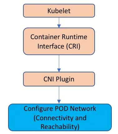
Relationship between Kubelet, CRI, CNI Plugin and Pod. Image by [Asifiqbal Pathan](https://medium.com/u/4a401eaf495c?source=post_page---user_mention--6d78456dbeb2--------------------------------)
## What’s a CNI Plugin?
Similar to CRI y CSI, [**CNI is a** CNCF Project](https://www.cni.dev/) which consists of a **specification and libraries** for writing Plugins that configure network interfaces in Linux containers, along with a number of other compatible plugins.
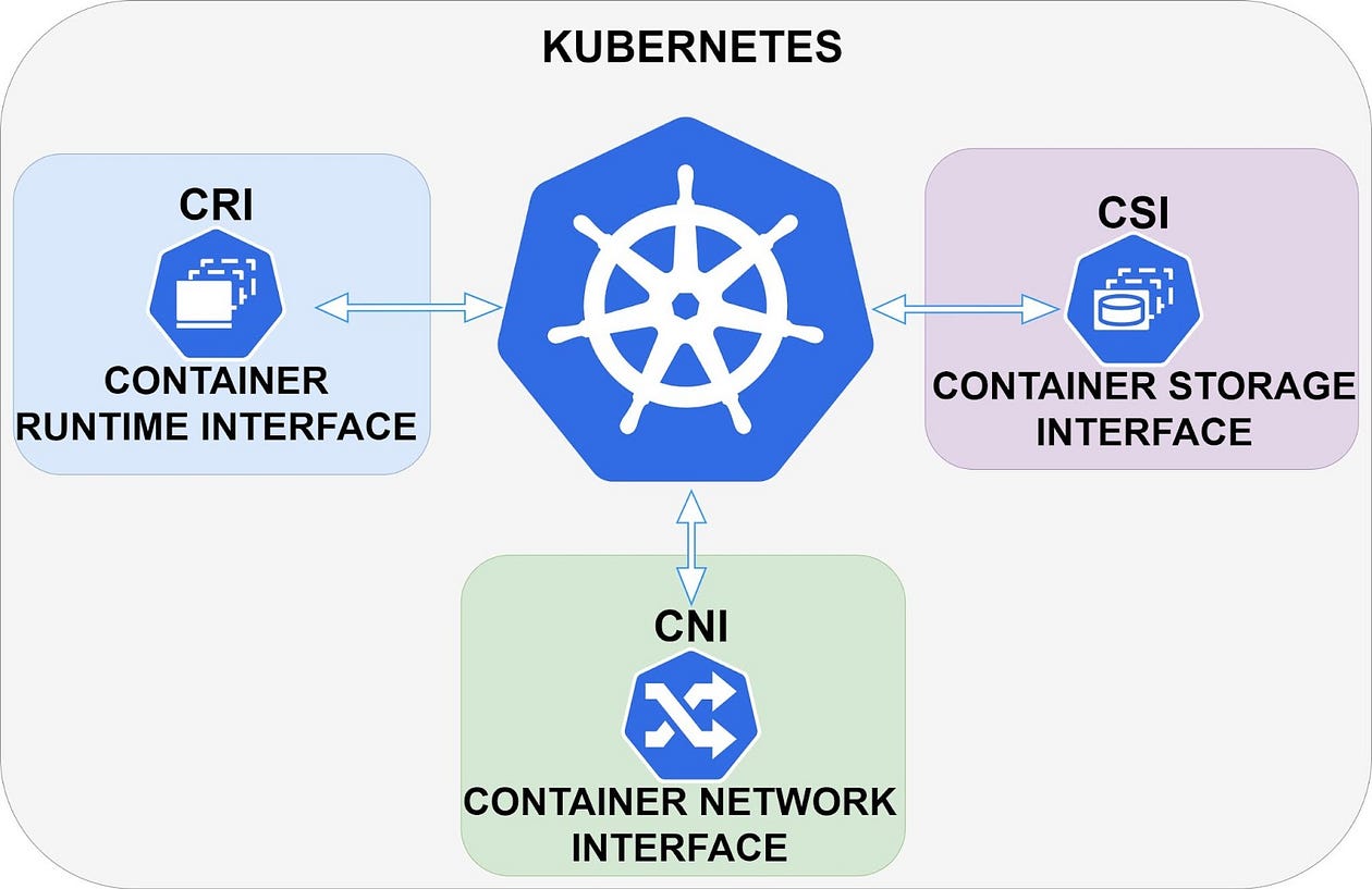
Kubernetes CNI, CRI and CSI. Image by [Daniel Guala](https://medium.com/u/c3c4b6bd459d?source=post_page---user_mention--6d78456dbeb2--------------------------------).
**CNI** deals only with the network connectivity of containers and the creation, modification, reading or deletion of allocated resources when the container is created or deleted. Because of this approach, CNI has a wide range of support and the specification is easy to implement.
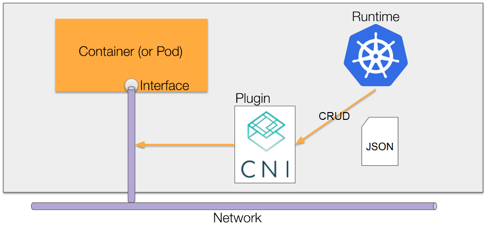
CNI-network. Image from [zhaohuabing.com](https://www.zhaohuabing.com/post/2020-02-21-network-service-mesh-english/)
## Default / Primary CNI Plugins CNI
The Primary or default CNI plugin is the main plugin that manages the networking in our K8s clusters.
There are multiple **CNI Plugins** with different implementations, but all primary plugins must resolve pod-to-pod communication **meeting the following requirements** from [Kubernetes](https://kubernetes.io/docs/concepts/services-networking/):
- All pods need a unique IP.
- Pods must communicate with other pods on all nodes without network address translation (NAT).
- Pods on a node’s host network can communicate with all pods on all nodes without using NAT.
- Agents on a node (e.g. system daemons, kubelet) can communicate with all pods on that node.
One way to group them is [based on native integration with Clouds](https://cloud.google.com/kubernetes-engine/docs/concepts/gke-compare-network-models#typical_network_model_implementations), thus obtaining 3 groups:
- **Fully integrated or flat:** Plugins that integrate directly and fully with the Cloud or VPC infrastructure of the K8s Cluster
- **Island-mode or bridged:** Plugins that use a SDN (Software Defined Network) isolated from the VPCs and fully managed by the plugins. Frequently used in on-premise implementations.
- **Isolated or air-gapped:** Not very common. Special cases.
Examples of this grouping can be seen below:
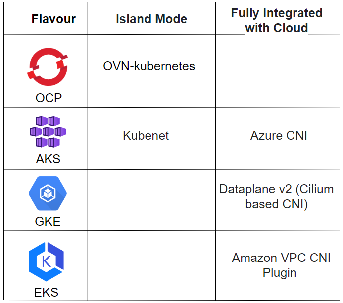
K8s Flavours and the Network Plugins they implement. Image by [Daniel Guala](https://medium.com/u/c3c4b6bd459d?source=post_page---user_mention--6d78456dbeb2--------------------------------).
## Additional Plugins
All plugins should have the main requirements covered, but **not all CNI plugins cover all needs from users** and, because of this reason, we have a wide variety of solutions.
You can have a **combination of different CNIs** for different functions, such as [Calico](https://docs.tigera.io/calico/latest/about/) for network policies and [Flannel](https://github.com/flannel-io/flannel) for pod network management.
It is not possible to have two different CNIs performing exactly the same functionality in the same cluster simultaneously.
A very interesting functionality is, for example, that a pod can **communicate directly with an external network** 😀
## Multus CNI

Multus CNI Logo
With [Multus CNI](https://github.com/k8snetworkplumbingwg/multus-cni), it is possible to configure additional networks alongside the default pod network, adding network interfaces to Pods on networks other than the main pod network.
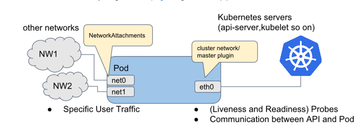
Image by [Pranav Deshpande](https://www.calsoftinc.com/blogs/a-primer-on-multus-cni.html).
The Multus CNI plugin acts as a **meta plugin** by calling other CNI plugins for advanced network functionalities.
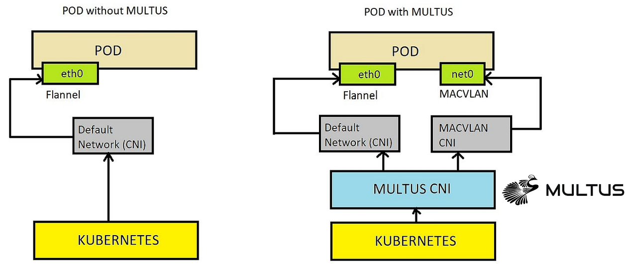
Image by [Nitin Sharma](https://medium.com/u/ac2c91daba8c?source=post_page---user_mention--6d78456dbeb2--------------------------------).
## Main Plugins
The following [CNI plugins are provided in OpenShift](https://docs.openshift.com/container-platform/4.14/networking/multiple_networks/understanding-multiple-networks.html) for Multus CNI to use when we need to add more networks to Pods or virtual machines in OpenShift Virtualization:
- **Bridge CNI:** to [configure an additional bridge network](https://docs.openshift.com/container-platform/4.14/networking/multiple_networks/configuring-additional-network.html#nw-multus-bridge-object_configuring-additional-network) to allow pods on the same host to communicate with each other and with the host.
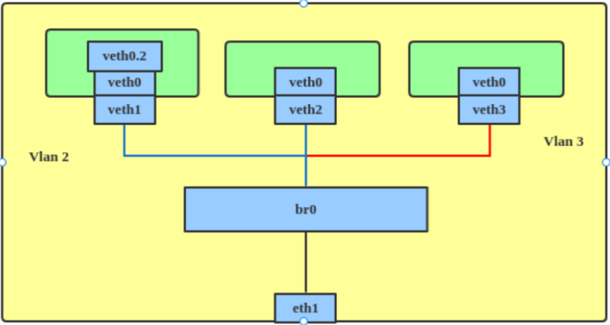
Image by [Red Hat](https://developers.redhat.com/articles/2022/04/06/introduction-linux-bridging-commands-and-features#vlan_filter).
- **host-device:** to allow pods to access a physical Ethernet network device on the Node.
- **Ipvlan:** to allow pods on one host to communicate with other hosts and pods on those hosts, similar to a macvlan-based add-on network. Unlike an additional macvlan-based network, each pod shares the same MAC address as the primary physical network interface.
- **vlan:** to enable isolation and VLAN-based network connectivity for pods.
- **Macvlan:** to allow pods on a host to communicate with other hosts and pods on those hosts via a physical network interface. Each pod that is connected to an additional macvlan-based network receives a unique MAC address.
- **Tap:** to create a tap device within the container namespace. A tap device allows user space programs to send and receive network packets.
- **SR-IOV:** to allow pods to connect to a virtual function (VF) interface on SR-IOV compliant hardware on the Node.
## NetworkAttachmentDefinitions
The Multus CNI plug-in is configured through `networkAttachmentDefinition` (`net-attach-def`or NAD) CRD. It can be configured in:
- **Pods:** to add an additional network to a Pod, it is sufficient to refer to it by an **annotation**.
- **VM:** in an OpenShift Virtualization VM, a network interface must be created and associated with the `net-attach-def`.
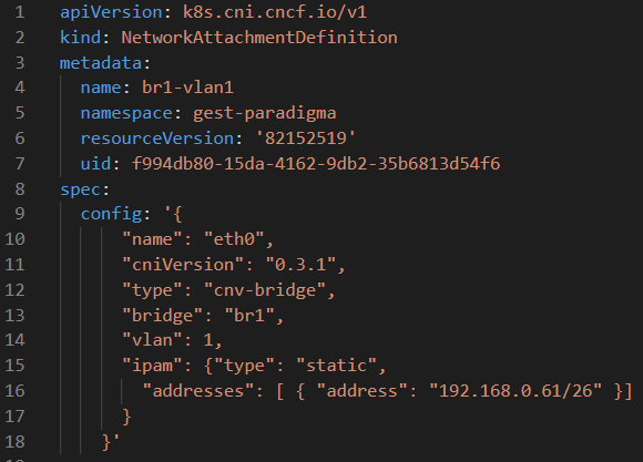
*net-attach-def example. Image by* [*Daniel Guala*](https://medium.com/u/c3c4b6bd459d?source=post_page---user_mention--6d78456dbeb2--------------------------------)*.*
## Related Operators
In this demo we will use Multus CNI and the following Operators.
## NMState Operator
The [NMState Operator](https://github.com/nmstate/kubernetes-nmstate) manages network configuration of nodes declaratively through the Kubernetes API via CRD.
The 3 main ones are:
- ***NodeNetworkState****:* reports the status of the network at that node.
- ***NodeNetworkConfigurationPolicy:*** describes the requested network configuration on the nodes. Through this object, the configuration of the node network can be updated, e.g. by adding or removing network interfaces.
- ***NodeNetworkConfigurationEnactment:*** It reports the network configuration applied at each node.
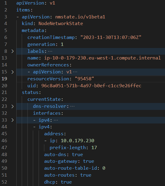
Node Network State Object example. *Image by* [*Daniel Guala*](https://medium.com/u/c3c4b6bd459d?source=post_page---user_mention--6d78456dbeb2--------------------------------)*.*
The **kubernetes-nmstate-operator** has been included as a component in OCP (OpenShift Container Platform) Virtualization until OCP version 4.10. [From this version onwards the Operator has to be installed separately.](https://docs.openshift.com/container-platform/4.11/virt/virt-4-11-release-notes.html#virt-4-11-removed)
NMState Operator in OpenShift OperatorsHub. Image by Red Hat.
## Openshift Virtualization Operator
In other [ParadigmaDigital blog posts](https://www.paradigmadigital.com/dev/virtualizacion-contenedores-kubernetes-despliegue-networking/) we have already told you about **OpenShift Virtualization** and the need for intermediate cloud native migration scenarios in which virtualized and containerised workloads coexist. This Operator allows you to host and manage virtualized workloads on the same platform as container-based workloads.
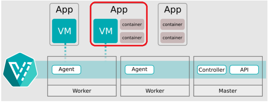
Image by [kubeVirt](https://kubevirt.io/user-guide/architecture/).
The technology behind OpenShift Virtualization is developed in the OpenSource community of [**KubeVirt**](https://kubevirt.io/).
OpenShift Virtualization Operator in OpenShift OperatorsHub. Image by Red Hat.
## Relationship between Multus CNI, NMState and OCP Virtualization.
At this point you will have several questions like why I have told you all this 😛.
Everything is related: With the NMState Operator we can declaratively manage physical network interfaces on the nodes and create resources (bridges) so that through Multus CNI we can add additional networks to OpenShift Virtualization pods or VMs.
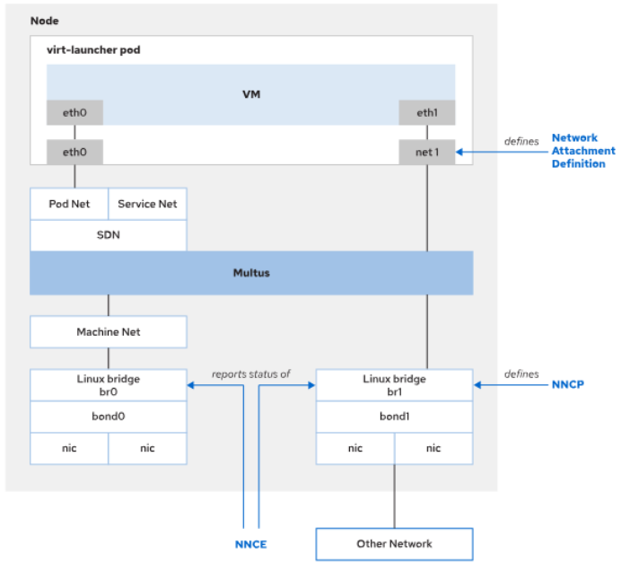
Image by Red Hat.
## Use Cases
Another question that may have arisen is “*Why would anyone need all this CRD mess?*”

We have seen in our clients the following use cases:
- **Segmentation and VLANs**: cases where you want to maintain network segmentation.
- **Special traffic case**: cases of special traffic, such as Multicast.
- **Static IP addressing**: For both offering and consuming services on different networks.
- **Migrations from virtualized loads to K8s**: as an intermediate step to eliminating networks and VLANs when migrating loads from VMware vSphere or Red Hat Virtualization to Kubernetes.
## Demo
In this demo:
- We will use an OpenShift 4.10 Single Node Cluster on AWS which has the OpenShift Primary Service Interface (ens6 with IP 10.0.179.230) and an additional VLAN1 Network Interface (eth2 with IP 192.168.0.60 ).
- We will [create a bridge called br1 on additional Interface](https://docs.openshift.com/container-platform/4.13/virt/virtual_machines/vm_networking/virt-attaching-vm-multiple-networks.html) using the NMState Operator CRDs.
- We will create a Multus `networkAttachmentDefinition` called `br1-eth2-net` associated to bridge `br1`
- We will create 1 VM and a Pod with additional interfaces that can be seen on the additional network VLAN1.
It would look something like this:
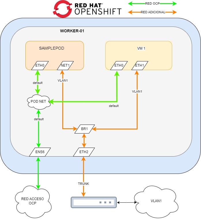
Image by [Daniel Guala](https://medium.com/u/c3c4b6bd459d?source=post_page---user_mention--6d78456dbeb2--------------------------------).
## NNS
Let’s look at the current state of the node’s network configuration and see that there is no reference to the br1 bridge we want to create.
In the following Yaml we see the relevant NNS information (there is omitted information about routes, dns, etc.):
```yaml
apiVersion: nmstate.io/v1beta1kind: NodeNetworkStatemetadata: name: ip-10-0-179-230.eu-west-1.compute.internalstatus: currentState: interfaces: - ipv4: address: - ip: 10.0.179.230 prefix-length: 17 auto-dns: true auto-gateway: true auto-route-table-id: 0 auto-routes: true dhcp: true enabled: true lldp: enabled: false mac-address: 0A:FA:D4:3D:B0:A7 mtu: 9001 name: ens6 state: up type: ethernet - ipv4: address: [] enabled: false ipv6: address: [] enabled: false lldp: enabled: false mac-address: 0A:DB:EC:A1:B5:DF mtu: 1500 name: eth1 state: down type: ethernet - ipv4: address: - ip: 192.168.0.60 prefix-lenPligth: 24 auto-dns: true auto-gateway: true auto-route-table-id: 0 auto-routes: true dhcp: true enabled: true lldp: enabled: false mac-address: 0A:AE:69:A1:16:FF mtu: 9001 name: eth2 state: up type: ethernet - ipv4: address: - ip: 127.0.0.1 prefix-length: 8 enabled: true ipv6: address: - ip: ::1 prefix-length: 128 enabled: true mac-address: "00:00:00:00:00:00" mtu: 65536 name: lo state: up type: unknown
```
```
## NNCP
Now we are going to use a `nodeNetworkConfigurationPolicy` object to create a bridge called `br1` on the `eth2` interface.
```yaml
apiVersion: nmstate.io/v1kind: NodeNetworkConfigurationPolicymetadata: name: br1-eth2-policyspec: nodeSelector: external-network: "true" desiredState: interfaces: - name: br1 description: Linux bridge with eth2 as a port type: linux-bridge state: up ipv4: dhcp: true enabled: true bridge: options: stp: enabled: false Port: - name: eth2
```
But before creating the above manifest, as you can see, the policy is associated to nodes through a `nodeSelector`, so let’s tag our node before creating the policy.
To do this, we run:
```
$ oc label node external-network='true' -l node-role.kubernetes.io/worker=''
```
And now we create the object with the above manifest through a file or through the web interface.
```
oc create -f br1-eth2-policy.yaml
```
Once created, we can view the status of the policy with the following command:
```
$ oc get nncpNAME STATUSbr1-eth2-policy Progressing
```
And to see the `nodeNetworkConfigurationEnactment` object that was automatically created by the policy with the command:
```
$ oc get nnceNAME STATUSip-10–0–179–230.eu-west-1.compute.internal.br1-eth2-policy Available
```
We will have to wait until both objects are in `Available` status.
## NNS and Node Allocatable
Once the above objects are available, we can look at the NNS and see if the new bridge has been created:
```
apiVersion: nmstate.io/v1beta1kind: NodeNetworkStatemetadata: name: ip-10-0-179-230.eu-west-1.compute.internalstatus: currentState: interfaces: - bridge: options: group-addr: 01:80:C2:00:00:00 group-forward-mask: 0 hash-max: 4096 mac-ageing-time: 300 multicast-last-member-count: 2 multicast-last-member-interval: 100 multicast-querier: false multicast-querier-interval: 25500 multicast-query-interval: 12500 multicast-query-response-interval: 1000 multicast-query-use-ifaddr: false multicast-router: 1 multicast-snooping: true multicast-startup-query-count: 2 multicast-startup-query-interval: 3125 stp: enabled: false forward-delay: 15 hello-time: 2 max-age: 20 priority: 32768 port: - name: eth2 stp-hairpin-mode: false stp-path-cost: 100 stp-priority: 32 vlan: enable-native: false mode: trunk trunk-tags: - id-range: max: 4094 min: 2 description: Linux bridge with eth2 as a port ipv4: address: - ip: 192.168.0.60 prefix-length: 24 auto-dns: true auto-gateway: true auto-route-table-id: 0 auto-routes: true dhcp: true enabled: true lldp: enabled: false mac-address: 0A:AE:69:A1:16:FF mtu: 9001 name: br1 state: up type: linux-bridge - ipv4: address: - ip: 10.0.179.230 prefix-length: 17 auto-dns: true auto-gateway: true auto-route-table-id: 0 auto-routes: true dhcp: true enabled: true lldp: enabled: false mac-address: 0A:FA:D4:3D:B0:A7 mtu: 9001 name: ens6 state: up type: ethernet - ipv4: address: [] dhcp: false enabled: false ipv6: address: [] autoconf: false dhcp: false enabled: false lldp: enabled: false mac-address: 0A:AE:69:A1:16:FF mtu: 1500 name: eth2 state: up type: ethernet - ipv4: address: - ip: 127.0.0.1 prefix-length: 8 enabled: true ipv6: address: - ip: ::1 prefix-length: 128 enabled: true mac-address: "00:00:00:00:00:00" mtu: 65536 name: lo state: up type: unknown
```
Once we confirm the bridge is created, we must check if the Kubernetes node detects this bridge as available for use. To do this we run the following command:
```
$ oc get no -o json | jq '.items[].status.allocatable'{ "attachable-volumes-aws-ebs": "25", "bridge.network.kubevirt.io/br1": "1k", "cpu": "71500m", "devices.kubevirt.io/kvm": "1k", "devices.kubevirt.io/sev": "0", "devices.kubevirt.io/tun": "1k", "devices.kubevirt.io/vhost-net": "1k", "ephemeral-storage": "96143180846", "hugepages-1Gi": "0", "hugepages-2Mi": "0", "memory": "196537932Ki", "ovs-cni.network.kubevirt.io/br0": "1k", "pods": "250"}
```
We can see how the bridge we have just created is available in the line `"bridge.network.kubevirt.io/br1": “1k”`. We should save this reference for later use with the `networkAttachmentDefinition`.
## NetworkAttachmentDefinition
Using the above reference we could create a network attachment definition as follows:
```
apiVersion: k8s.cni.cncf.io/v1kind: NetworkAttachmentDefinitionmetadata: annotations: k8s.v1.cni.cncf.io/resourceName: bridge.network.kubevirt.io/br1 name: br1-eth2-net namespace: defaultspec: config: >- {"name":"br1-eth2-net","type":"cnv-bridge","cniVersion":"0.3.1","bridge":"br1","macspoofchk":false,"ipam":{}}
```
If we create it this way, we will have to manage the IP configuration separately.
With the Network Attachment Definitions, it is possible to configure the added interfaces to request IPs via DHCP, if you have configured a DHCP server on the additional network, using the following in the config json section:
```
{"name":"br1-eth2-net","type":"cnv-bridge","cniVersion":"0.3.1","bridge":"br1","macspoofchk":false,"ipam":{"type" : "dhcp"}}
```
Or even use static IPs , gateways, routes, etc.:
```
{"name":"br1-eth2-net","type":"cnv-bridge","cniVersion":"0.3.1","bridge":"br1","macspoofchk":false,"ipam":{"type": "static", "addresses": [ { "address": "192.168.0.61/26" }] }}
```
**This should be taken into account when configuring IPs in VMs and Pods.**
As we do not have DHCP available on the additional network and to demonstrate the capabilities of the `net-attach-def`, we will create 2 objects.
- One for the **POD** which will include a static IP **192.168.0.61**.
```
apiVersion: k8s.cni.cncf.io/v1kind: NetworkAttachmentDefinitionmetadata: annotations: k8s.v1.cni.cncf.io/resourceName: bridge.network.kubevirt.io/br1 name: net-br1-podspec: config: >- {"name":"net-br1-pod","type":"cnv-bridge","cniVersion":"0.3.1","bridge":"br1","macspoofchk":true,"ipam":{"type":"static","addresses":
```
- One for a **VM** that will include a static IP **192.168.0.62**.
```
apiVersion: k8s.cni.cncf.io/v1kind: NetworkAttachmentDefinitionmetadata: annotations: k8s.v1.cni.cncf.io/resourceName: bridge.network.kubevirt.io/br1 name: net-br1-podspec: config: >- {"name":"net-br1-pod","type":"cnv-bridge","cniVersion":"0.3.1","bridge":"br1","macspoofchk":true,"ipam":{"type":"static","addresses": [ { "address": "192.168.0.62/24" }] }}
```
**Let’s remember:**
> if we had a DHCP, it would be enough to attach pod and vm to the same `net-attach-def` indicating that the IPAM is of type DHCP.
## VM and Pod Configuration
It’s time to add the network we have configured to VMs and Pods.
## VM
To add an additional network on a VM, we need to associate the `net-attach-def` we created earlier with a new network interface on a powered off OpenShift Virtualization Virtual Machine.
We can do this through the VM manifest or the web console, in this case we will use the console, clicking “*Add Network Interface*”
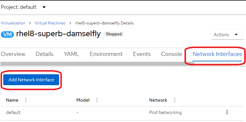
OpenShift Virtualization Virtual Machine. Screenshot of Red Hat OpenShift.
Filling the needed data and “Add”:
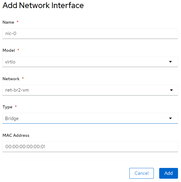
OpenShift Virtualization Virtual Machine. Screenshot of Red Hat OpenShift.
Once added, we should configure which IP we want to assign to the VM, if it has not been done through the `net-attach-def`.
As we have done it through the NAD there is nothing more to do, but we could [configure the IP of the VM using cloud-init](https://docs.openshift.com/container-platform/4.13/virt/virtual_machines/vm_networking/virt-configuring-ip-for-vms.html) by modifying the VM’s manifest.
```
kind: VirtualMachinespec: template: spec: volumes: - cloudInitNoCloud: networkData: | version: 2 ethernets: eth1: addresses: - 10.10.10.14/24
```
Or by managing e.g. through `configMaps`objects or cloud-init scripts that such a file exists in the route `/etc/sysconfig/network-scripts/ifcfg-eth1`.
```
TYPE=EthernetPROXY_METHOD=noneBROWSER_ONLY=noBOOTPROTO=noneIPADDR=192.168.0.62PREFIX=26DEFROUTE=noIPV4_FAILURE_FATAL=noIPV6_DISABLED=yesIPV6INIT=noNAME=eth1UUID=bcc1d1f7–93c1–3029–9183–260631483bddDEVICE=eth1ONBOOT=yesAUTOCONNECT_PRIORITY=-999HWADDR=00:00:00:00:00:02
```
We confirm that the VM has the IP Address we want:
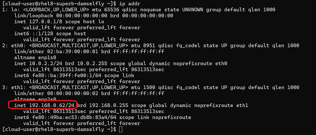
Image by [Daniel Guala](https://medium.com/u/c3c4b6bd459d?source=post_page---user_mention--6d78456dbeb2--------------------------------).
## POD
To create a pod with an IP Address on an additional network, in this case having used the NAD to manage the IP Address, it is as simple as creating the following manifest:
```
apiVersion: v1kind: Podmetadata: name: samplepod annotations: k8s.v1.cni.cncf.io/networks: '[{ "name": "net-br1-pod", "default-route": ["192.168.0.2"] }]'spec: containers: - name: samplepod command: ["/bin/ash", "-c", "trap : TERM INT; sleep infinity & wait"] image: alpine
```
We confirm this by logging into the pod and looking at the network interfaces and seeing that in addition to the pod network there is another interface with the IP Address we defined in the NAD:
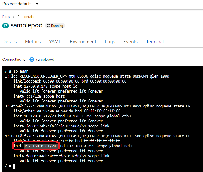
OpenShift Virtualization Virtual Machine. Screenshot of Red Hat OpenShift.
## Test
We will check that we can reach resources on the new network by simply pinging it.
Ping from Pod to VM:
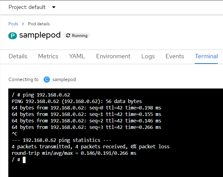
OpenShift Virtualization Virtual Machine. Screenshot of Red Hat OpenShift.
Ping from VM to Pod:
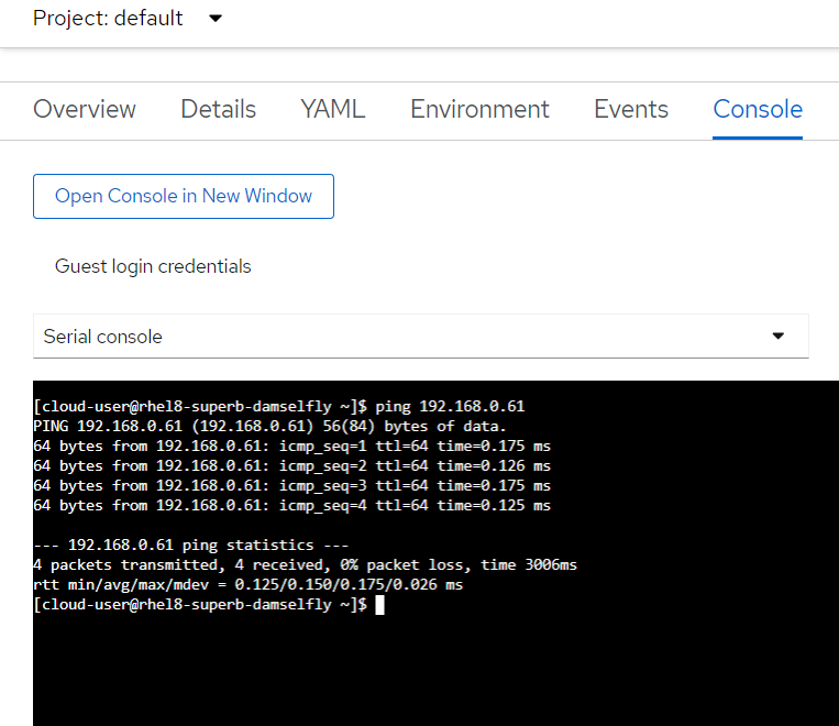
OpenShift Virtualization Virtual Machine. Screenshot of Red Hat OpenShift.
## Conclusion
Adding additional networks to the network of Pods in Kubernetes opens up a range of possibilities to solve complex requirements and challenges in our clusters. In these cases, Multus CNI is our best ally.
https://medium.datadriveninvestor.com/can-a-kubernetes-pod-have-more-than-one-network-attached-6d78456dbeb2